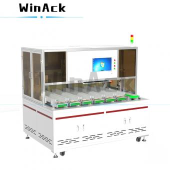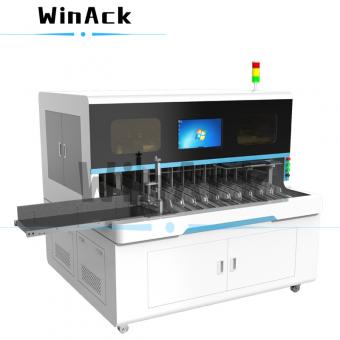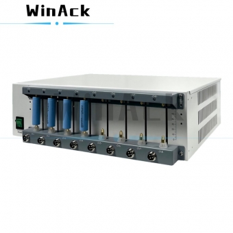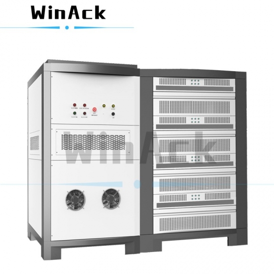

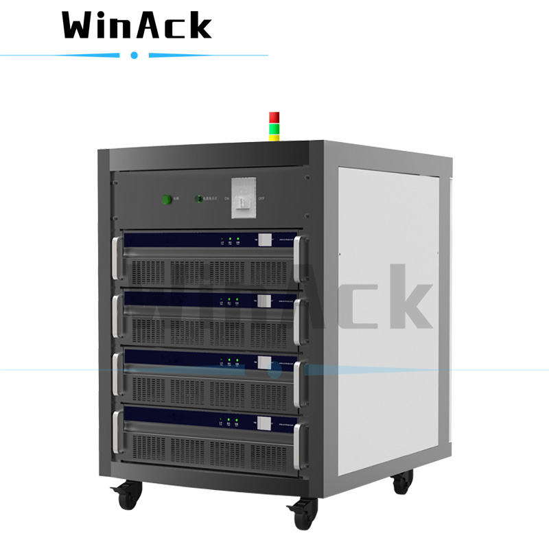
The lithium-ion battery testing equipment is a professional battery tester machine with single-channel independent control and user-friendly operating software in English.
Model:
WA-BTS-60V300ACertificate:
CE Certificate issued by TÜV, UL CertificateTest channels:
1CH/Cabinet or 2CH/Cabinet (Customizable)Voltage range/CH:
0V~60V (Customizable)Voltage accuracy:
±0.05% F.S.Current range/CH:
±300A (Customizable)Current accuracy:
±0.05% F.S.Product Detail
Professional Battery Tester Machine
Lithium-ion Battery Testing Equipment
Functional description:
The lithium-ion battery testing equipment is a professional battery tester machine, which integrates charge-discharge cycle test function, charge-discharge data monitoring function and battery module/battery pack performance test function.
User-friendly operating software in English, powerful testing functions, high testing accuracy, good equipment stability, and energy-saving technology with energy feedback, these are the features of this professional battery tester machine.
Applicable range:
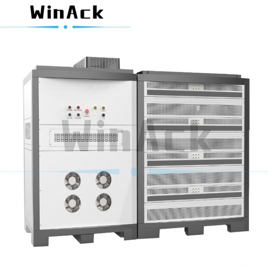
This lithium-ion battery testing equipment is mainly used for charge-discharge cycle test and performance test of battery modules and battery packs.
In addition, it can also perform working condition simulation test, which is a professional electric vehicle battery test system.
Technical specifications
|
Product name |
Battery Test Systems |
|||||||
|
Product model |
WA-BTS-60V300A |
|||||||
|
Number of test channels |
1CH/Cabinet or 2CH/Cabinet |
|||||||
|
1. |
Sound |
≤75dB (Measured at the rear 1m from the battery test device) |
||||||
|
2. |
Heat dissipation |
Air forced cooling |
||||||
|
3. |
Energy feedback function |
Battery energy discharged to the AC grid (DC-AC mode) |
||||||
|
4. |
IP Rating |
IP20 |
||||||
|
5. |
Charge optimal conversion efficiency |
≥90% (From power grid to battery; Optimal power point) |
||||||
|
6. |
Discharge optimal conversion efficiency |
≥90% (From battery to power grid; Optimal power point) |
||||||
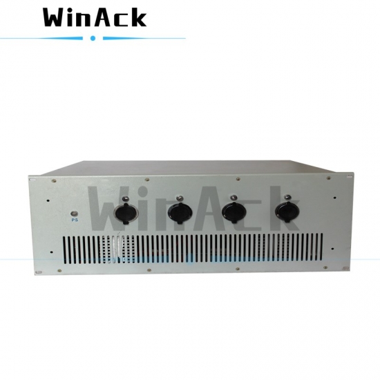
|
7. |
Output line |
5m of copper wire as standard (copper nose, tinned terminals) |
||||||
|
8. |
Tri-color light |
Tri-color light, buzzer |
||||||
|
9. |
Emergency stop button |
Standard |
||||||
|
AC side input indicator |
||||||||
|
10. |
Input power |
Three-phase five-wire, 380VAC±10%, frequency of 50Hz/60HZ ±5Hz (Customizable) |
||||||
|
11. |
Power factor |
≥0.99(Full load) |
||||||
|
12. |
The Harmonic Distortion (THD) |
≤5%(Full load) |
||||||
|
13. |
Isolation mode |
ACDC High Frequency Isolation |
||||||
|
14. |
Input protection |
Anti-surge, anti-islanding, over/under frequency protection, over/under voltage protection, phase loss protection, AC short circuit protection |
||||||
|
DC side output indicator |
||||||||
|
15. |
Number of DC-side channels |
1CH/Cabinet or 2CH/Cabinet |
||||||
|
16. |
Main channel |
Control method: Independent control of each channel |
||||||
|
17. |
Single channel input impedance |
≥1MΩ |
||||||
|
18. |
Voltage range (DC) |
0V~60V |
||||||
|
19. |
Voltage output accuracy |
±0.05% FS (0℃~45℃) |
||||||
|
20. |
Voltage resolution |
1mV |
||||||
|
21. |
Current range |
±300A |
||||||
|
22. |
Min. current output |
50mA |
||||||
|
23. |
Current output accuracy |
±0.05% FS |
||||||
|
24. |
Current resolution |
1mA |
||||||
|
25. |
Max. Output power |
18KW (1CH Cabinet) |
||||||
|
36KW (2CH Cabinet) |
||||||||
|
26. |
Power resolution |
1W |
||||||
|
27. |
Power accuracy |
±0.1%FS |
||||||
|
28. |
Parallel connection |
Available (2CH Cabinet) |
||||||
|
29. |
The rise and fall time of current |
≤5ms |
10%~90% (Battery load, without overshoot) |
|||||
|
30. |
The switch time between charge and discharge |
≤10ms |
+90%~-90% (Battery load, without overshoot) |
|||||
|
31. |
Ripple coefficient |
≤0.5%FS (load connected to battery) |
||||||
|
Communication mode |
||||||||
|
32. |
Communication mode of upper computer |
Based on TCP/IP protocol |
||||||
|
33. |
Communication interface |
Ethernet |
||||||
|
34. |
Baud rate of lower computer |
100M~1000M self-adaptive |
||||||
|
35. |
Baud rate of upper computer |
10M~1000M self-adaptive |
||||||
|
36. |
Networking |
LAN through switches and routers |
||||||
|
37. |
Communication expansion (Optional) |
Support CAN, CANFD interface and BMS communication |
DBC import |
|||||
|
Support RS485, RS232, LIN interface and BMS communication |
Support for custom document editing |
|||||||
|
Support one-wire, UART interface and BMS communication |
Support for custom document editing |
|||||||
|
38. |
Peripheral expansion |
Support linkage of temperature chamber, water-cooler or other peripheral equipment |
||||||
|
Environment requirement and device dimension |
||||||||
|
39. |
Working temperature |
0℃~45℃ |
||||||
|
40. |
Storage temperature |
-20℃~50℃ |
||||||
|
41. |
Relative humidity |
≤85%RH (non-condensing) |
||||||
|
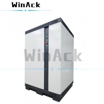
42. |
Dimension |
1CH Cabinet: W900mm*D1090mm*H1029mm |
||||||
|
2CH Cabinet: W1035mm*D1035mm*H1706mm |
||||||||
|
43. |
Weight |
1CH Cabinet: 350KG |
||||||
|
2CH Cabinet: 650KG |
||||||||
|
Auxiliary equipment (Optional) |
||||||||
|
44. |
Temperature range |
Option 1: -20℃~120℃(NTC) |
||||||
|
Option 2: -40℃~200℃(T thermocouple) |
||||||||
|
45. |
Temperature accuracy |
Option 1: ±1℃ version(NTC) |
||||||
|
Option 2: ±0.5℃(T thermocouple) |
||||||||
|
46. |
Temperature sensor |
Option 1: NTC |
||||||
|
Option 2: T thermocouple |
||||||||
|
47. |
Voltage range |
Option 1: 0V~5V |
||||||
|
Option 2: -5V~10V |
||||||||
|
48. |
Voltage acquisition accuracy |
±0.05%FS |
||||||
|
49. |
Digital IO |
DO for dry contact DI for input judgement, low level when voltage below1.5V, voltage of 0~20V for input |
||||||
|
50. |
Monitor box (redundant protection) |
Hardware level independent anti-cell overcharge and over-discharge device. Supports voltage upper and lower limit setting and monitoring as well as control dry contacts. |
||||||
|
51. |
PWM card |
Square wave output |
||||||
|
Frequency |
0~30KHz |
|||||||
|
Duty ratio |
(2KHz~10KHz)10~90% |
|||||||
|
(1KHz~2KHz)1~99% |
||||||||
|
Duty ratio accuracy |
±1us |
|||||||
|
Output voltage |
0~13V |
|||||||
|
Output voltage accuracy |
±200mV |
|||||||
|
Graded protection mechanism |
||||||||
|
52. |
AC side hardware level protection |
Grid over/under-voltage protection |
||||||
|
Anti-surge protection |
||||||||
|
Anti-islanding protection |
||||||||
|
Over/under frequency protection |
||||||||
|
Phase loss protection |
||||||||
|
AC short-circuit protection |
||||||||
|
Lightning protection |
||||||||
|
Hardware over-temperature derating protection |
||||||||
|
Self-check protection |
||||||||
|
Emergency stop protection |
||||||||
|
53. |
DC side hardware level protection |
Bus-bar over/under-voltage protection |
||||||
|
Hardware over-temperature protection |
||||||||
|
Voltage reverse protection |
||||||||
|
Power reverse protection |
||||||||
|
Voltage line misconnection protection |
||||||||
|
Power line misconnection protection |
||||||||
|
Self-check protection |
||||||||
|
Loose cable protection |
||||||||
|
54. |
Integrated battery-side protection |
Battery total voltage upper/ lower limit protection |
||||||
|
Battery cell voltage upper/ lower limit protection |
||||||||
|
Battery temperature upper limit protection |
||||||||
|
Battery current upper limit protection |
||||||||
|
Battery capacity upper/ lower limit protection |
||||||||
|
Voltage difference protection 1 (Total voltage difference protection between main sampling and auxiliary sampling) |
||||||||
|
Voltage difference protection 2 (Total voltage difference protection between main acquisition and BMS sampling) |
||||||||
|
Battery BMS drop protection |
||||||||
|
CAN communication drop protection |
||||||||
|
Voltage fluctuation exception protection |
(customizable voltage range) |
|||||||
|
Current fluctuation exception protection |
(customizable current range) |
|||||||
|
Temperature fluctuation exception protection |
(customizable temperature range) |
|||||||
|
55. |
Peripheral equipment |
Temp chamber fault linkage protection |
(customizable range) |
|||||
|
Water-cooler fault linkage protection |
(customizable range) |
|||||||
|
Peripheral IO signal linkage protection |
Nebula IO card configured (Optional) |
|||||||
|
Auxiliary cell voltage sampling linkage protection (independent redundancy protection) |
Nebula monitor card configured (Optional) |
|||||||
|
Peripheral communication disconnection linkage protection |
||||||||
|
56. |
Software protection |
Resume of power outage data |
|
|||||
|
Offline test function on the host computer |
Supports offline operation for12 hours |
|||||||
|
Channel data migration |
When a channel is damaged, the incomplete data can be migrated to another channel for continuation |
|||||||
|
Step function characteristic |
||||||||
|
57. |
Min. interval of data recording |
10ms |
||||||
|
58. |
Min. interval of simulation time |
50ms |
||||||
|
59. |
Min. pulse width |
50ms |
||||||
|
60. |
Programmable step |
≧99999 |
||||||
|
61. |
Cycle index |
99999 |
||||||
|
62. |
Max.number of nested loop layers |
≧20 |
||||||
|
63. |
Charge discharge mode |
CC: Constant current charge |
The parameters support three modes of input: numeric, variable and expression. Current additionally supports multiplier input mode. |
|||||
|
CV: Constant voltage charge |
||||||||
|
CCCV: Constant current constant voltage charge |
||||||||
|
CP: Constant power charge |
||||||||
|
DC: Constant current discharge |
||||||||
|
DP: Constant power discharge |
||||||||
|
DR: Constant resistance discharge |
||||||||
|
Pulse |
||||||||
|
Working condition simulation |
||||||||
|
Current ramp |
||||||||
|
DCIR |
||||||||
|
Standing |
||||||||
|
64. |
Cut-off condition (jump condition, if condition) |
Voltage |
||||||
|
Current |
||||||||
|
Capacity (total capacity, charging capacity, discharging capacity) |
||||||||
|
Energy (total energy, discharge energy, charging energy) |
||||||||
|
Time (total time, single step time) |
||||||||
|
SOC (RT-SOC real-time calculation) |
||||||||
|
Power |
||||||||
|
Rate of change (voltage/ current/temperature change rate) |
||||||||
|
Cycle index |
||||||||
|
Auxiliary cell voltage difference |
||||||||
|
Auxiliary cell temperature difference |
||||||||
|
DV voltage difference |
||||||||
|
CAN message signal (Customizable) |
||||||||
|
COM message signal (Ethernet, serial port) (Customizable) |
||||||||
|
Custom variable (Customizable) |
||||||||
|
Real-time arithmetic expressions (Customizable) |
||||||||
|
Digital switch signal (Nebula IO card required) |
||||||||
|
Shared variable (Other channel status signal) |
||||||||
|
Min.auxiliary cell voltage |
||||||||
|
Max.auxiliary cell voltage |
||||||||
|
65. |
Execution Type |
Jump |
||||||
|
Pause |
||||||||
|
And condition |
||||||||
|
Alarm |
||||||||
|
Digital IO signal control |
Connected to peripherals, access control, fire alarm, etc. |
|||||||
|
CAN command sending |
Control of any peripheral, temperature chamber, water cooler, battery, etc. |
|||||||
|
COM command sending |
Control of any peripheral, temperature chamber, water cooler, battery, etc. |
|||||||
|
Set variable (assignment) |
||||||||
|
Set shared variable |
||||||||
|
Battery basic parameter CAN message sending |
||||||||
|
SOC calibration |
||||||||
|
Limit function (Current, power) |
||||||||
|
66. |
Working condition step |
Current simulation (Support 50ms simulation) |
Supports 10 million line loads in a single step |
|||||
|
Power simulation (Support 50ms simulation) |
||||||||
|
Capacity simulation |
||||||||
|
Import of text condition files such as EXCEL, TXT, etc. and support for editing of condition files |
||||||||
|
67.
|
Pulse step |
Current pulse |
Supports 1 million different pulses in a single pulse step |
|||||
|
Power pulse |
||||||||
|
Min.pulse width of 50ms |
||||||||
|
One pulse step supports continuous switching from charge to discharge |
||||||||
|
Support for pulse step editing, graphic preview |
||||||||
|
68. |
DCIR step |
Support for custom fetch points, hardware real-time calculations |
||||||
|
Support for software custom fetch points and software calculation of post data |
||||||||
|
69. |
Step color definition |
Custom color setting according to step types of charging, discharging and standing |
||||||
|
70. |
Battery model storage |
When editing the step, select the already established battery information library, or create a new battery library, to automatically generate global upper and lower limits for the selected battery, and to alarm against batteries that are out of the device output range. |
||||||
|
71. |
Lower computer model storage |
When editing the step, select the already established lower computer information library, or create a new battery library, to automatically generate global upper and lower limits for the selected battery and lower computer, and to alarm against batteries that are out of the device output range. |
||||||
|
72. |
Test step calibration |
The software automatically checks the logic of the edited steps and provides automatic pop-ups. |
||||||
|
73. |
DBC file import |
File editing, saving and import |
||||||
|
74. |
Serial port protocol self-editing |
File editing, saving and import |
||||||
|
75. |
Basic setting for global parameters |
Voltage upper/lower limits |
||||||
|
Current upper/lower limits |
||||||||
|
Capacity upper/lower limits |
||||||||
|
Temperature upper/lower limits |
||||||||
|
Global recording condition (Time, voltage, current interval) |
||||||||
|
76. |
Advanced setting for global parameters |
Global if conditions all types configurable, charge global, discharge global, single step type global. User can configure voltage change rate,current change rate,and temperature change rate according to global parameters |
||||||
|
77. |
Single step parameter setting |
Voltage upper/lower limits (Effective globally when not set) |
||||||
|
Current upper/lower limits |
||||||||
|
Capacity upper/lower limits |
||||||||
|
Temperature upper/lower limits |
||||||||
|
Charging capacity and energy reset (Before the start of a single step) |
||||||||
|
Discharging capacity, energy reset (Before the start of a single step) |
||||||||
|
Total capacity and energy reset (Before the start of a single step) |
||||||||
|
Step duration reset (Before the start of a single step) |
||||||||
|
78. |
Advanced function for single step (supported on some models) |
Dynamic cell voltage limited power mode |
||||||
|
Dynamic cell temperature limited power mode |
||||||||
|
Dynamic cell temperature limited current mode |
||||||||
|
Follow BMS signal function (current following, power following) |
During constant current charging and discharging, the BMS values are called directly for follow up, allowing for max. charging and discharging |
|||||||
|
Matrix look-up function (SOC\temperature real-time look-up) |
Multiple matrix tables can be bound in a single step, running different matrix tables as required |
|||||||
|
Limit value function (BMS limit value, limit current value, set limit value) |
||||||||
|
79. |
Custom variables |
Conventional variables, BMS variables and peripheral parameters can be used to form new variables. Parameters (battery parameters, BMS values, peripheral parameters) for a specific step can be extracted for data calculation and used as jump and cut-off conditions for subsequent steps. |
Supports four fundamental operations, find the average value, Max. Value, Min.value, absolute value, integer and exponential; |
|||||
|
80. |
SOC real-time calculation |
After executing the calibrated SOC, the subsequent steps can directly call up the SOC calculation in real time and use it as a judgement condition |
||||||
|
81. |
Expressions (equations) |
Can be used as a regular real time variable, a custom variable or as an if condition after four fundamental operation |
Real-time expressions |
|||||
|
82. |
Linkage |
Temperature chamber linkage |
1. When the channel reaches a certain condition, set the temperature of the temperature chamber. 2. Stop charging when the temperature chamber fails. |
|||||
|
Multi-battery with one temperature chamber linkage |
1. When the battery in channel A reaches a certain condition, it will enter the waiting mode, when B battery also reaching to a certain condition, the temperature chamber will be triggered to adjust the temperature. |
|||||||
|
Water-cooler linkage |
1. When the channel reaches a certain condition, set the parameter of the water-cooler. 2. Stop charging when the water-cooler fails. |
|||||||
|
Inter channel status linkage |
For example, when the channel A charges to a certain state and stops, then channel B starts discharging and discharges to a certain state; |
|||||||
|
External system linkage |
External system signals (bus, IO) participate in the channel linkage |
|||||||
|
83. |
Idle recording |
When the normal operation of the channel ends, or alarm protection occurs, the equipment will continuously record the battery parameters; when there is an exception in the static parameters (such as thermal diffusion, voltage exceptions) all running channels of the entire cabinet can be stopped urgently and an alarm can be issued to facilitate later problem tracing. |
||||||
|
84. |
Current grading |
Intelligent current grading can be activated for parallel models. |
Activated in CC, current simulation mode |
|||||
|
MES uploading (Optional) |
||||||||
| 85. |
MES uploading function |
Data uploading MES according to customers’ specific needs. |
||||||
High-quality battery life cycle tester manufacturer, professional battery life analyzer supplier, with test software and test data processing software, please contact us for more details.
The battery system tester is a professional EV battery testing equipment and battery energy storage system tester with powerful test functions. It is suitable for the test of high-power battery packs.
The battery cycler is a professional battery module test equipment and battery pack test system, suitable for EV battery, energy storage battery pack and regenerative battery pack, etc.
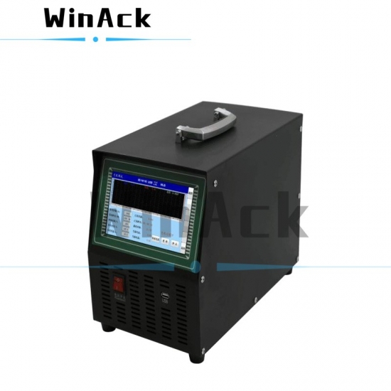
The battery module/pack test system is a portable battery charge discharge test equipment, as well as a professional EV battery tester, and is compatible with electrical networks globally.
The battery charge discharge test equipment is a professional regenerative battery pack test system for quality control and performance testing. The voltage, current, and power ranges can be customized.
The battery aging machine is essentially a battery charge discharge machine, used to simulate and accelerate the aging process of the batteries to test the performance of the finished battery packs.
This professional and powerful power bank tester is specially designed for battery aging, capacity testing, quality inspection and cycle life testing of portable power banks.
This high voltage battery cycler is a regenerative battery charger and discharger with powerful test functions and capabilities, suitable for testing batteries of Electric Vehicles, Electric Buses and Energy Storage Systems.


 IPv6 network supported