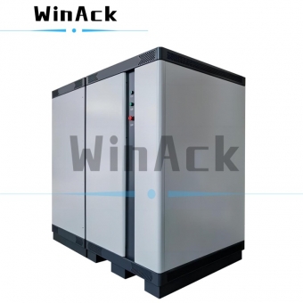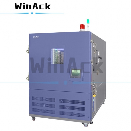
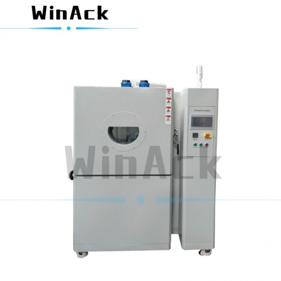
Altitude thermal chamber is a professional battery safety testing equipment integrating high altitude simulator and thermal test chamber, and can be linked with battery cycler to make battery testing easier.
Model:
WA-ST-216ATCEffective Volume:
216L (Customizable)Temp. Range:
-20℃ ~ +150℃ (Customizable)Temp. Fluctuation:
≤ ±0.5℃Air Pressure Range:
50KPa ~ Standard atmospheric pressure (Customizable)Pressure Deviation:
≤ ±2KPaDelivery time:
45~60 days (Negotiable)Product Detail
Altitude Thermal Chamber
High Altitude Simulator & Thermal Test Chamber
Functional description:
The altitude thermal chamber can simulate specific environmental conditions test on battery cells, battery modules, battery packs and other materials to evaluate their environmental adaptability and reliability.
Such as high altitude simulation test, thermal cycling test, thermal stability test, high temperature ambient simulation test, low temperature ambient simulation test, high and low temperature cycle temperature change test, test under a single condition or test under a combination of multiple conditions.
Applicable range:
The altitude thermal chamber is used to simulate the safety or stability of batteries or other materials, and the main environments simulated are altitude and high and low temperatures.
Applicable test standards:
1) GB/T2423.1-2008(IEC60068-2-1:2007) Environmental testing - Part 2: Test methods - Tests A: Cold
2) GB/T2423.2-2008(IEC60068-2-2:2007) Environmental testing for electric and electronic products Test methods - Tests B: Dry heat
3) GB/T2423.21-2008(IEC60068-2-13:1983) Environmental testing - Part 2: Test methods - Test M: Low air pressure
4) GB/T2423.25-2008(IEC60068-2-40:1976) Environmental testing - Part 2: Test methods - Test Z/AM: Combined cold/low air pressure tests
5) GB/T2423.25-2008(IEC60068-2-40:1976) Environmental testing - Part 2: Test methods - Test Z/BM: Combined dry heat/low air pressure tests
6) Etc.
Features:
1)The altitude thermal chamber has a wide adjustable temperature range, from -20°C to +150°C.
2)The overall internal pressure-bearing structure is adopted to meet the long-term use.
3)The internal chamber of the thermal vacuum testing equipment is made of SUS304# stainless steel, which is resistant to high and low temperatures.
4)The testing holes and communication interface are reserved, which can be connected with the battery cycler.
5)The altitude thermal chamber is equipped with a variety of protection devices with complete protection functions, which effectively guarantees the safe and reliable operation of the equipment.
6)The application of refrigeration and cold balance technology can save about 30% of electric energy and effectively reduce the cost of use.
7)TIG seamless welding to ensure absolute sealing and no leakage.
Technical specifications
|
1. Product Overview |
|||||||||||||||||||||||
|
1.1 Product Name |
Altitude Thermal Chamber |
||||||||||||||||||||||
|
1.2 Product Model |
WA-ST-216ATC |
||||||||||||||||||||||
|
1.3 Effective Volume |
216L |
||||||||||||||||||||||
|
1.4 Inner Dimension |
W600*D600*H600mm |
||||||||||||||||||||||
|
1.5 Overall Dimension |
W940*D2117*H1670mm Kindly reminder: The actual product shall prevail. |
||||||||||||||||||||||
|
1.6 Power |
8KW |
||||||||||||||||||||||
|
1.7 Max. Current |
15A |
||||||||||||||||||||||
|
1.8 Power Source |
Three-phase, 380VAC±10%, 50Hz±0.5Hz |
||||||||||||||||||||||
|
1.9 Weight |
Approx 1260KG |
||||||||||||||||||||||
|
1.10 Noise |
≤75dB |
||||||||||||||||||||||
|
2. Performance at Ambient Air Pressure |
|||||||||||||||||||||||
|
2.1 Condition |
Environment temp.: +5℃~+35℃, Relative humidity: ≤85%. No load (Without specimen in the testing zone) |
||||||||||||||||||||||
|
2.2 Temp. Range |
-20℃ ~ +150℃ |
||||||||||||||||||||||
|
2.3 Temp. Fluctuation |
≤ ±0.5℃ |
||||||||||||||||||||||
|
2.4 Temp. Deviation |
≤ ±2.0℃ |
||||||||||||||||||||||
|
2.5 Temp. Gradient |
≤ ±1.0℃ |
||||||||||||||||||||||
|
2.6 Temp. Heating Time |
-20℃→100℃: ≥2℃/min, average, non-linear, no load |
||||||||||||||||||||||
|
2.7 Temp. Cooling Time |
100℃→-20℃: ≥1℃/min, average, non-linear, no load |
||||||||||||||||||||||
|
2.8 Wind Speed |
<1.7m/s |
||||||||||||||||||||||
|
3. Performance at Low Air Pressure |
|||||||||||||||||||||||
|
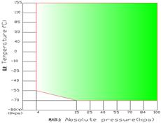
3.1 Altitude and Pressure |
|
||||||||||||||||||||||
|
3.2 Temp.-Air Pressure Integrated Control |
|
||||||||||||||||||||||
|
3.3 Air Pressure Range |
50KPa ~ Standard atmospheric pressure |
||||||||||||||||||||||
|
3.4 Pressure Deviation |
≤ ±2KPa |
||||||||||||||||||||||
|
3.5 Pressure Reducing Time |
101KPa→50Kpa: ≤30min |
||||||||||||||||||||||
|
3.6 Pressure Recovery Time |
≤10KPa/min |
||||||||||||||||||||||
|
4. Structure & Material |
|||||||||||||||||||||||
|
4.1 Structural Features |
The overall internal pressure-bearing structure is adopted to meet the long-term use. |
||||||||||||||||||||||
|
4.2 External Chamber |
Cold-rolled steel plate with painting, thickness ≤1.2mm, can ensure long-term use. |
||||||||||||||||||||||
|
4.3 Internal Chamber |
SUS304# high & low temperature resistance stainless steel, thickness≥5mm. TIG seamless welding to ensure absolute sealing and no leakage. |
||||||||||||||||||||||
|
4.4 Air Conditioning System |
The air conditioning system is located at the rear of the internal chamber and includes the following components: temperature sensor, forced convection circulation fan, nickel-cadmium alloy helical heater, evaporator. The air in the altitude thermal chamber is processed by the air conditioning system for internal circulation to achieve heating, cooling and other functions. |
||||||||||||||||||||||
|
4.5 Insulation Material |
The thickness of the insulation layer: 150mm, all of which are made of flame-retardant materials. The outer layer is bonded with high-density polyurethane for heat insulation and moisture resistance, and the inner layer is insulated with glass wool felt. |
||||||||||||||||||||||
|
4.6 Refrigeration Unit |
The single-stage refrigeration system composed of semi-hermetic piston compressors mainly includes refrigeration components such as compressors, condensers, evaporators, and throttle valves. |
||||||||||||||||||||||
|
4.7 Controller |
Includes various components for control and related alarms, such as controller modules, fuses, motor starters, circuit breakers, contactors, relays, transformers, DC power supplies, etc. |
||||||||||||||||||||||
|
4.8 Chamber Door |
Full opening single wing door with double layer silicone rubber seal and door lock. The equipped door lock can be pressed to prevent the door from leaking; the equipped explosion-proof chain can improve the safety performance during battery testing. |
||||||||||||||||||||||
|
4.9 Observation Window |
With vacuum glass observation window on the door; and door frame with electric heat resistant, anti-frosting, anti-condensing devices, ensures clear observation of the specimen under testing. |
||||||||||||||||||||||
|
4.10 Testing Hole |
Each 1 DN100mm testing hole on left and right of the chamber, with silicon seal and stainless-steel cover. |
||||||||||||||||||||||
|
4.11 Sample Holder |
Equipped with 2 stainless steel plate stamping parts racks, bearing ≥30kg. |
||||||||||||||||||||||
|
4.12 Control Panel |
LCD touch screen programmable controller |
||||||||||||||||||||||
|
4.13 Power Distribution Control Cabinet |
The main power circuit breaker, controller, power distribution board, cooling fan, and digital over-temperature protector are installed inside. |
||||||||||||||||||||||
|
5. Electrical Control System |
|||||||||||||||||||||||
|
5.1 Controller |
PLC controller, simultaneously controls temperature and air pressure. |
||||||||||||||||||||||
|
5.2 Screen Display Function |
l 7-inch color display screen; l Direct display of temperature and pressure set value (SV) and process value (PV); l Can display test program number, segment, remaining time and cycle times, running time; l Test program editing and graphic curve display; l Individual program editing screen, each page can input 4 segments of temperature and time; l Fixed point or program action status display; |
||||||||||||||||||||||
|
5.3 Program Capacity and Control Functions |
l Available programs: 120 groups at most, one program can be composed of 1 to 100 segments, a total of 1200 segments. l Repeatable execution of commands: each command can be up to 999 times, the program slope can be set by the time axis, the maximum time between programs can be set at 99 hours and 99 minutes, and the minimum is one minute. l It has functions such as editing, clearing, and inserting, with 4 groups of time signal output control (which can control the ON/OFF action of the object to be tested), with 9 groups of PID parameter settings, and has the function of skipping and holding during program execution. l With power-off program memory, it will automatically start and continue to execute program functions after power-on. l With scheduled start and shutdown functions. |
||||||||||||||||||||||
|
5.4 Communication Function |
l It can be connected to an industrial PC to display curves and obtain data. l It can be connected to monitoring and remote-control systems, such as battery cycler systems. l Multiple machines can be controlled synchronously. |
||||||||||||||||||||||
|
5.5 Data Read |
Read set values, process values and operating curves. |
||||||||||||||||||||||
|
5.6 Display Resolution |
Temperature: 0.01℃; Time: 1min. |
||||||||||||||||||||||
|
5.7 Power-off Memory Function |
The power-off recovery mode can be set as: warm start, cold start and stop. |
||||||||||||||||||||||
|
5.8 Scheduled Power-on Function |
The power-on time can be set at will, and the machine will run automatically after the power is turned on. |
||||||||||||||||||||||
|
5.9 Temperature Sensor |
PT100 platinum resistance |
||||||||||||||||||||||
|
5.10 Software Usage Environment |
Support English version of PC Windows operating system |
||||||||||||||||||||||
|
5.11 Auxiliary function |
l Fault alarm and cause, processing prompt function; l Power-off protection function; l Upper and lower limit temperature protection function. |
||||||||||||||||||||||
|
5.12 Heater |
Nickel-chromium alloy heating wire, high efficiency and long service life. |
||||||||||||||||||||||
|
5.13 Heating Control Method |
The temperature controller controls the heater output according to the set temperature and the process temperature. |
||||||||||||||||||||||
|
6. Refrigeration Control System |
|||||||||||||||||||||||
|
6.1 Air Cooling Method |
Single stage compressor refrigeration system |
||||||||||||||||||||||
|
6.2 Compressor |
Cryogenic compressors made in Europe |
||||||||||||||||||||||
|
6.3 Cooling Method |
Air cooling |
||||||||||||||||||||||
|
6.4 Evaporator |
High efficiency multi-segment fin type evaporator |
||||||||||||||||||||||
|
6.5 Throttling Device |
Thermal expansion valve and capillary |
||||||||||||||||||||||
|
6.6 Oil Separator |
The refrigerated oil droplets mixed with the high-temperature and high-pressure refrigerant gas discharged from the compressor are separated and returned to the compressor's curved rail cavity for lubrication and cooling of the compressor. |
||||||||||||||||||||||
|
6.7 Filter Drier |
Absorb the residual moisture and acidic substances in the refrigerant of the refrigeration system, and filter out the solid impurity particles and copper chips in the system, so as to protect the normal operation of the expansion valve and capillary. |
||||||||||||||||||||||
|
6.8 Refrigerant |
Environment friendly refrigerant HFC R404a (Other options are available) |
||||||||||||||||||||||
|
6.9 Refrigeration System Features |
l The entire system pipelines are subjected to a leak test of 22kg of ventilation and pressure. l The heating and cooling systems are completely independent. l All the action procedures of the refrigeration system are completely controlled by the microcomputer controller. l There is a water collecting tray at the bottom of the compressor, which can collect the condensation water produced by frost. l The compressor comes with a PTC temperature sensor, which realizes over-temperature protection when the compressor is over-temperature. l The compressor has its own oil pressure protector to achieve compressor oil pressure protection. l The high-pressure protection device monitors the pressure of the refrigerant during the working process of the equipment. Once the refrigerant pressure is higher than the limit pressure of the system, an alarm will be issued immediately and the power will be cut off until the fault is eliminated. l The application of refrigeration and cold balance technology can save about 30% of electric energy and effectively reduce the cost of use. |
||||||||||||||||||||||
|
7. Vacuum System |
|||||||||||||||||||||||
|
7.1 Vacuum Pump |
The vacuum is realized by a single-stage rotary vane pump, and the precise control of the pressure is realized by starting the on-off of the butterfly valve. |
||||||||||||||||||||||
|
7.2 Vacuum Valve |
Select high-quality vacuum accessories to ensure the vacuum degree of the altitude thermal chamber. |
||||||||||||||||||||||
|
7.3 Vacuum Clamp |
Use high-quality stainless-steel clamps and high temperature resistant fluor rubber sealing rings. |
||||||||||||||||||||||
|
7.4 Vacuum Sensor |
The pressure is precisely controlled with a high-precision pressure sensor. |
||||||||||||||||||||||
|
7.5 Magnetic Fluid |
High-quality magnetic fluid is used to ensure the reliability and tightness of the connection. |
||||||||||||||||||||||
|
8. Safety Protection System |
|||||||||||||||||||||||
|
8.1 Refrigeration System |
l Compressor overheating protection l Compressor overload protection l Compressor overpressure protection l Compressor overtemperature protection |
||||||||||||||||||||||
|
8.2 Test Chamber |
l Extreme digital display over-temperature protection l Pressure automatic balance protection l Bottom protection prevents water accumulation l Explosion-proof chains are specially equipped for battery testing. |
||||||||||||||||||||||
|
8.3 Heating System |
l Heating tube extreme over temperature protection l Heating tube short circuit protection. |
||||||||||||||||||||||
|
8.4 Power Supply |
l Overall power overload and short circuit protection l Control circuit overload or short circuit protection. |
||||||||||||||||||||||
|
8.5 Circulation Fan |
l Fan overload l Fan short circuit l Fan reverse protection. |
||||||||||||||||||||||
|
8.6 Vacuum System |
Vacuum pump overload protection. |
||||||||||||||||||||||
|
9. Environmental Conditions and Installation Site Requirements |
|||||||||||||||||||||||
|
9.1 Operating Temperature |
5℃~30℃ |
||||||||||||||||||||||
|
9.2 Relative Humidity |
≤85%RH (No condensation) |
||||||||||||||||||||||
|
9.3 Storage temperature |
0℃~45℃ When the ambient temperature is lower than 0°C, the water retained in the equipment should be drained before the equipment is stopped for a long time, so as to prevent the water in the pipeline from freezing and causing damage to the pipeline. |
||||||||||||||||||||||
|
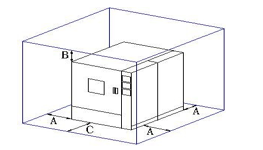
9.4 Installation site |
l It must be a flat and vibration-free ground; l Keep away from heat sources and flammable and explosive substances; l There are no strong electromagnetic radiation sources nearby; l Cannot be exposed to direct sunlight, and maintain indoor air circulation; l The installation site needs to be clean, and it cannot be installed in a dusty place or dust outlet; l The ground bearing capacity of the site: not less than 600kg/m2; l Allow adequate maintenance space around the chamber:
A: not less than 600mm, B: not less than 600mm, C: not less than 1200mm. |
||||||||||||||||||||||

Thermal cycling test chamber is a professional program-controlled high and low temperature test chamber, which can be linked with the battery cell cycler for battery testing projects.
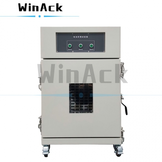
Explosion-Proof Test Chamber is a professional battery test safety chamber used for battery overcharge tests, battery forced discharge tests, battery over-discharge protection tests.
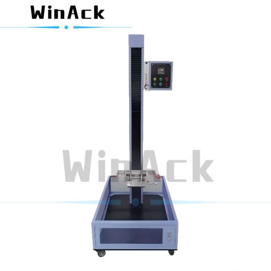
Lithium battery drop tester is used for simulating battery free fall drop test and battery drop impact test in standards such as IEC62133, UL 2054 and UL 1642, etc.
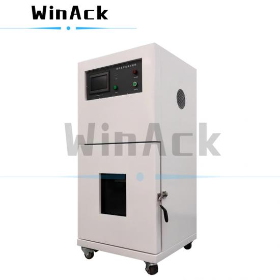
High altitude simulation chamber simulates air transport under low pressure conditions and conducts altitude simulation tests and low pressure tests in standards such as UN38.3, IEC 62281 and UL 1642, etc.
The lithium ion battery vibration tester machine is used to simulate vibration during transport or use to perform vibration tests in standards such as UN38.3, IEC62133, UL 1642 and UL 2054, etc.
High altitude simulation chamber simulates air transport under low pressure conditions and conducts altitude simulation tests and low pressure tests in standards such as UN38.3, IEC 62281 and UL 1642, etc.
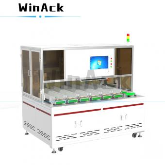
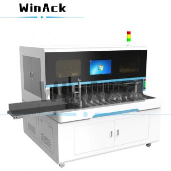
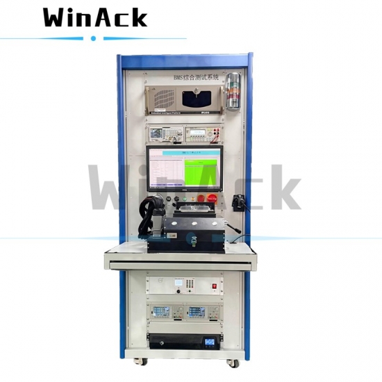
Battery management system tester is a professional BMS functional test stand for EOL quality testing of BMS manufacturers and incoming inspection of ESS/EV battery pack manufacturers.
Lithium battery drop tester is used for simulating battery free fall drop test and battery drop impact test in standards such as IEC62133, UL 2054 and UL 1642, etc.


 IPv6 network supported